The performance of a centrifugal pump can be given by its speed, the total head, and the required flow. This information can be derived suitably by referring to the manufacturer's published curves (Iso-efficiency Curves). In this context, the specific speed of a pump is used to describe the geometry of the pump, and is an important factor in considering the number of stages necessary, as well as the arrangement of the impellers (series or parallel).
The specific speed, also known as , has a direct bearing on pump efficiency, and in general, efficiency is said to increase as increases.
Specific Speed
The Specific Speed of a Centrifugal Pump is the speed in r.p.m. at which a similar model of the Pump would need to run when of such a size as to deliver unit quantity against unit head.
Each type of pump (Radial Flow, Mixed Flow, Axial Flow, etc.) has it's own characteristic value of . 'Similar' includes both dynamic and geometric similarity, i.e., similar velocity triangles, with all relevant velocities proportional to each other.
The speed of an object is the magnitude of its velocity (the rate of change of its position).
A pump is a device used to move fluids, such as liquids, gases or slurries.
but
and
Since
where Constant.
But and are by definition unity.
Therefore the Specific Speed:
Notes
a) is based on the values of , , and at the design point, i.e. at maximum efficiency.
b) is not dimensionless and will have different values in the different measuring systems (in the foot/slug/second system is in r.p.m., is in feet and is in gallons/second).
The Dimensions of are:
Thus could be made dimensionless by dividing by and it would still be a Constant.
For example, Addison's Shape Number is:
c) Comparison of and (Imperial Units)
Thus for a particular machine:
d) Specific Speeds for Differing pump types (Imperial Units)
Centrifugal Pumps Type Specific Speed
Radial Flow 800 - 2000
Mixed Flow 2000 - 4000
Axial Flow 4000 - 8000 and Screw Pump
Propeller Pump 8000 - 16,000 (High and Low )
e) Variation of efficiency with Specific Speed:
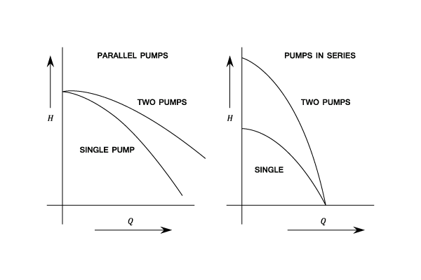
f) Multi-Staging:
When the head to be developed is too great for a single impeller (from an efficiency point of view this is about 150 ft.), several impellers in series are mounted on the same shaft. These are usually of the radial flow type. The flow through each stage is the same and the total head developed is divided equally between the stages.
Example:
[imperial]
Example - Example 1
Problem
It is required to pump 900 gallons per min. through a height of 300 ft.
If is 1500 how many
stages are required if the motor speed is to be 1200 r.p.m.
Workings
And:
Therefore Head/Stage is:
Thus, the number of stages is:
Solution
The number of stages is:
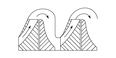
g) Pumps in Parallel
When the quantity to be pumped is high and would require a very large pump, several pumps in parallel may be preferred, possibly running on the same shaft. Each must develop the required head and will deliver an equal share of the required discharge.
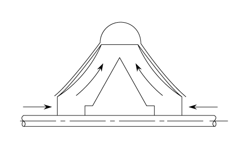
h) Double Entry (double suction) Impeller
In a single stage pump, double entry impellers are frequently used to overcome the problem of end thrust. For Multistage pumps the single acting impellers can be arranged back to back.
For comparison of specific speeds between single and double acting impellers, the double type is regarded as two single acting impellers back to back, i.e. in the Specific Speed equation the value of would be half of the actual value.
Performance Of A Given Pump Under Different Conditions
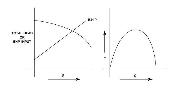
The Characteristic Curves For A Centrifugal Pump
The characteristic curves for a Centrifugal Pump are plotted from a constant speed or on a capacity basis. There is no means of altering the Guide Vane angles as in a Turbine and the only control is the Delivery Valve. If only one motor speed is possible then there will be only one performance curve.
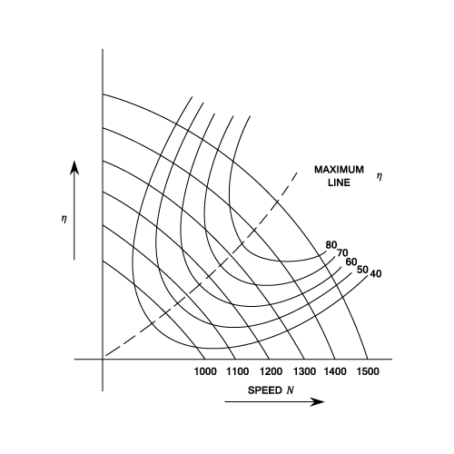
Iso-efficiency Curves
If the driving speed of the motor can be vared, then tests of the performance at several speeds can be carried out and a chart drawn to show performance at all possible operating conditions.
Estimating The Performance At Different Speeds (unit Conditions)
If the performance curves for a particular pump are known at a particular speed, the corresponding curves can be found at any speed by using similarity conditions.
For dynamically similar conditions:
(where Constant)
Also from equations (4) and (6) same as above:
Or,
From Equations ( ) and ( )
And from the same equations:
Example:
[imperial]
Example - Example 1
Problem
A Pump delivers 400 g.p.m against a head of 110 ft. when running at 1.400 r.p.m. A geometrically
similar pump 1.5 times the linear size operates at 1200 r.p.m.
Determine the head and discharge of the larger pump assuming that both pumps are working at their
points of maximum efficiency.
<table>
<tr><td></td><td>Pump1</td><td>Pump 2</td></tr>
<tr><td>Discharge Q</td><td>400 g/min.</td><td>?</td></tr>
<tr><td>Delivery Head H</td><td>110 ft</td><td>?</td></tr>
<tr><td>Speed N</td><td>1400 r.p.m</td><td>1200 rpm</td></tr>
<tr><td>( Size) D</td><td>X</td><td>1.5</td></tr>
</table>
Workings
Assume that the pumps are working under dynamically similar conditions.
From equation (1)
i.e.
Therefore:
Also from equation (6)
Therefore:
Solution
The head is
The discharge is
Limitations Of The Simple Impeller Theory
An impeller is a rotor inside a tube or conduit used to increase the pressure and flow of a fluid.
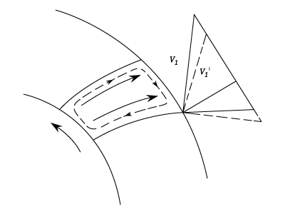
Secondary Circulatory Motion
Due to the inertia of water, the water within the passages of the impeller rotate relative to the passage in a direction opposite to that of the impeller rotation. The effect of this is to decrease the effective outlet angle from to and thus to decrease to ( and remain unchanged).
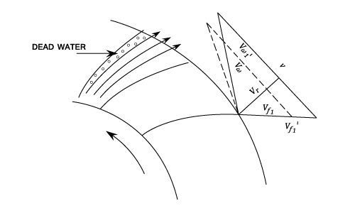
Flow Breakaway
Flow concentrates in the trailing part of the passage, thus leaving an area of dead water behind the vanes. The effect is to increase the velocity of flow from to and thus to decrease to ( and remain unchanged)
It can be seen that the actual head transmitted by the vanes to the water:
is less than that indicated by the Euler Equation which is based on ideal velocity triangles from an infinite number of Vanes.
This does NOT imply a loss in the head produced or in the efficiency but simply means that both input and output power are less because less power has been transmitted by the vanes to the water.


is based on the values of
,
, and
at the design point, i.e. at maximum efficiency. b)
and it would still be a Constant. For example, Addison's Shape Number is:
and
(Imperial Units)
d) Specific Speeds for Differing pump types (Imperial Units) Centrifugal Pumps Type Specific SpeedThus for a particular machine:e) Variation of efficiency with Specific Speed:
 When the head to be developed is too great for a single impeller (from an efficiency point of view this is about 150 ft.), several impellers in series are mounted on the same shaft. These are usually of the radial flow type. The flow through each stage is the same and the total head developed is divided equally between the stages.
unchanged)
Equations (1),(2),(3) enable the characteristics at any speed to be calculated from test results at a single speed. i.e.
i.e.
^2\left(\frac{D_2}{D_1}&space;\right)^2)
^2\left(\frac{3}{2}&space;\right)^2=\frac{81}{49}) Therefore:
Therefore:
 Also from equation (6)

^2\left(\frac{D_2}{D_1}&space;\right)^3\;=\;\frac{12}{14}\left(\frac{3}{2}&space;\right)^3\;=\;\frac{81}{28}) Therefore:
Therefore:

to
and thus to decrease
to
(
and
remain unchanged).
to
and thus to decrease
remain unchanged) It can be seen that the actual head transmitted by the vanes to the water:
is less than that indicated by the Euler Equation which is based on ideal velocity triangles from an infinite number of Vanes.This does NOT imply a loss in the head produced or in the efficiency but simply means that both input and output power are less because less power has been transmitted by the vanes to the water.