The head loss due to friction in Pipes with uniform run off. Also covered are Tapered Pipes
View other versions (5)
Introduction
In the supply of water for Domestic, Commercial and Irrigation purposes, it is common for water to be taken from the pipe line, in many places along the length. Due to the viscosity of a fluid in motion, energy is dissipated as the fluid circulates through the pipe. As a result,the pressure of the fluid at various points along the pipeline will vary.
This section analyses the head loss in uniform pipe.
HeadLoss (or friction head or resistance head) is due to the frictional forces acting against a fluid's motion by the container.
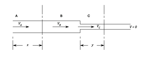
Let the rate of flow at the pipe entry be and that at the pipe exit be .
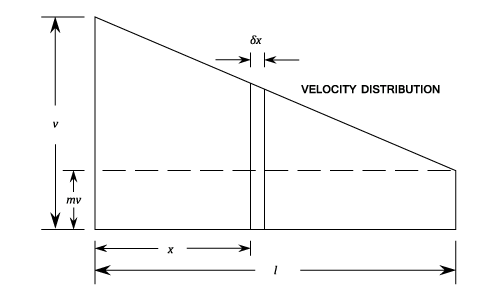
Consider a short length of pipe at a distance from the entry point.
The velocity at this section is:
rr,
The frictional head lost over:
Thus the Total Head Lost over the pipe length is given by:
It can be seen that the above equation assumes that not all the water is discharged over the length . If however this is not the case, = 0.
And the Head Lost:
i.e. A third of the head loss which would have been lost with a uniform velocity of flow .
Example:
[imperial]
Example - Example 1
Problem
A horizontal water-main comprises 5000 ft. of 6 in pipe followed by 3000 ft. of 4 in. pipe (=0.007 for both). All the water is drawn off at a uniform rate per ft. length of pipe.
If the total input is , find the total pressure drop along the main, neglecting all losses except friction. Also draw the Hydraulic Gradient diagram taking the pressure head at inlet as 180 ft.
Workings
The velocity of flow at is:
As the water is drawn off at a steady rate, the rate of flow at the end of the 6 in. pipe is given by :
The quantity flowing
And the rate of flow
Since:
And:
Substituting the above values into equation (1) of Total Head Lost:
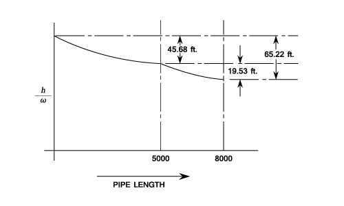
The Hydraulic Gradient
Three points on the graph are already known. The inlet pressure of 180 ft. and consequently the pressures at the end of the 6 in. pipe and the 5 in. pipe. It is now necessary to establish the pressure varies between these points.
enters the pipe and it is all drawn off at a uniform rate over the complete length of the pipe. Thus at any point distant from the start of the pipe the quantity flowing will be:
When is in the 6 in. diameter section of the pipe:
Hence the head lost due to friction between the inlet and the point ( being in the 6 in. section of the pipe) is given by Equation (1) of Total Head Lost:
i.e.
Thus the pressure at which is ft. from the is given by:
At the start of the 4 in. pipe the velocity of flow is 3.88 ft./sec. and at the end of the pipe the velocity is zero. Hence the velocity at any point from is given by:
Hence the frictional head lost over the distance is given by:


 =0.007 for both). All the water is drawn off at a uniform rate per ft. length of pipe.
 , find the total pressure drop along the main, neglecting all losses except friction. Also draw the Hydraulic Gradient diagram taking the pressure head at inlet as 180 ft.
 is:
is:
^2}=4.584\;ft./sec.)
 And the rate of flow
^2}=1.719) Since:
Since:

 And:
And:
 Substituting the above values into equation (1) of Total Head Lost:
For the 4 in length of pipe
Substituting the above values into equation (1) of Total Head Lost:
For the 4 in length of pipe  = 0 since all the water is used up and nothing flows out of the end of the pipe. The velocity of flow is now given by:
^2}=3.88\;ft./sec.) Using equation (1) of Total Head Lost again:
Hence the total head lost
Using equation (1) of Total Head Lost again:
Hence the total head lost
 The Hydraulic Gradient
Three points on the graph are already known. The inlet pressure of 180 ft. and consequently the pressures at the end of the 6 in. pipe and the 5 in. pipe. It is now necessary to establish the pressure varies between these points.
The Hydraulic Gradient
Three points on the graph are already known. The inlet pressure of 180 ft. and consequently the pressures at the end of the 6 in. pipe and the 5 in. pipe. It is now necessary to establish the pressure varies between these points.
 from the start of the pipe the quantity flowing will be:
 When
When  Hence the head lost due to friction between the inlet and the point
 +)
^2&space;\right&space;)=)
+)
^2))
\;ft.) Thus the pressure at
Thus the pressure at  which is
  is given by:
At the start of the 4 in. pipe the velocity of flow is 3.88 ft./sec. and at the end of the pipe the velocity is zero. Hence the velocity at any point
is given by:
At the start of the 4 in. pipe the velocity of flow is 3.88 ft./sec. and at the end of the pipe the velocity is zero. Hence the velocity at any point  from
from  is given by:

 Hence the frictional head lost over the distance
 +)
^2&space;\right&space;)=)
) Which can be written as:
Which can be written as: