Key facts
For a magnetic circuit with two symmetrical parallel parts, the total number of ampere-turns/meter is given by:
where is the number of ampere-turns/meter for the path of length , and so on.
For a magnetic circuit with two asymmetrical parallel parts, the total flux is given by:
where is the magnetic reluctance.
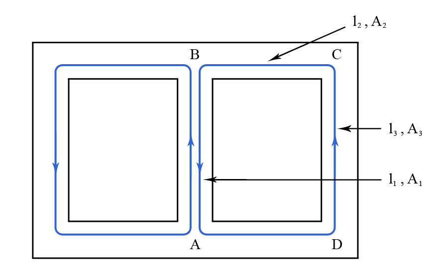
Consider the symmetrical magnetic circuit diagramed in Figure 1, where the path is of length and area , the path is of length and area , the path is of length and area , and so on.
Figure 1
In this case, we can write that the magnetic flux density for the path is:
We also consider the number of ampere-turns/meter for the path as being .
Following a similar reasoning, we can write that the magnetic flux density for the path is:
while the number of ampere-turns/meter is .
We can apply the same rationale for the other segments as well. We can thus write that the total number of ampere-turns/meter is:
As the circuit is symmetrical, it is easy to find out how the magnetic flux divides. For example, in Figure 1 the magnetic flux in the center is twice that in each side.
Magnetic Circuits With Asymmetrical Parallel Parts
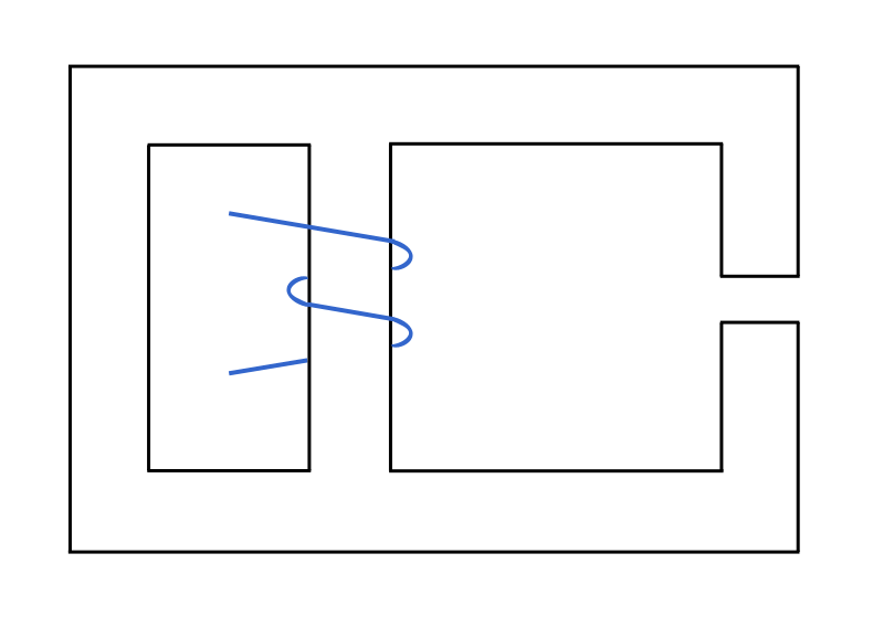
Consider the asymmetrical circuit diagramed in Figure 2.
Figure 2
In this case, due to the lack of symmetry, . There are two methods which allow you to calculate the magnetic flux on each parallel part.
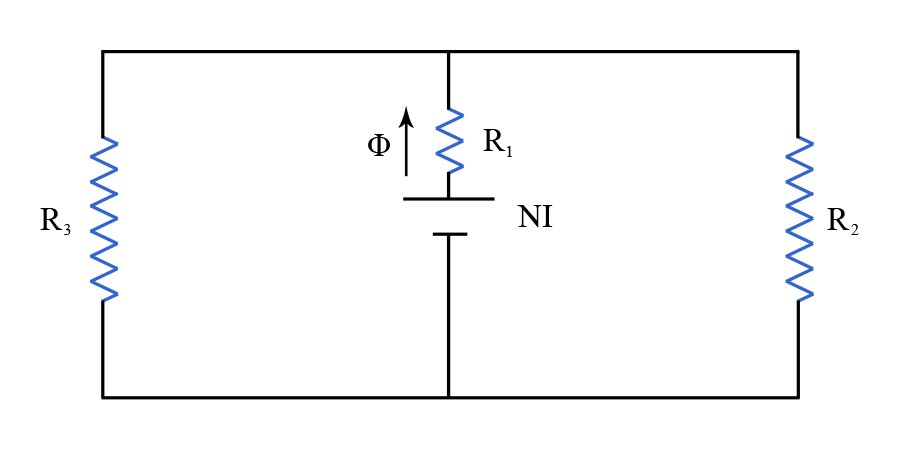
The first method assumes that there is no magnetic saturation. The problem is then worked out by using magnetic permeabilities. For a magnetic circuit as the one diagramed in Figure 3, we obtain that:
where is the magnetic reluctance (for a more detailed discussion on the magnetic reluctance see Magnetic Reluctance ).
Figure 3
The second method is more of a trial-and-error method. It first implies dividing up the magnetic flux by hinting the right values, and then calculating for all paths. These should be equal, and if they are not, then you have to re-adjust the initial division of the magnetic fluxes.


 where
where  is the number of ampere-turns/meter for the path
  of length
  , and so on.
For a magnetic circuit with two asymmetrical parallel parts, the total flux is given by:
, and so on.
For a magnetic circuit with two asymmetrical parallel parts, the total flux is given by:
 where
where  is the magnetic reluctance.