The drawing shows the Bending Moment diagram and the shape of a deflected beam between two point and .
MISSING IMAGE!
23287/MoA-020.png cannot be found in /users/23287/MoA-020.png. Please contact the submission author.
The area of the Bending Moment diagram is and its centroid is at a distance of from a chosen line .
A beam is a horizontal structural element that is capable of withstanding load primarily by resisting bending. The bending force induced into the material of the beam as a result of the external loads, own weight, span and external reactions to these loads is called a bending moment.
The tangents at and to the elastic line, cut off an intercept on .
i.e. The increase of slope between any two points on a beam is equal to the net area of the Bending Moment diagram between those two points divided by .
If is the radius of curvature of the beam at some point between and , then the angle between the tangents at the end of a short length where .
The intercept of these tangents on is and since the slope everywhere is small:
i.e. The intercept on a given line between the tangents to the beam at any two points and is equal to the net moment about that line of the Bending Moment diagram between and divided by .
Account has to be taken of positive and negative areas and frequently it is convenient to break down the Bending Moment diagram into a number of simple figures, so that the moment is obtained from
The interecept is positive when the tangent at strikes below the tangent at .
This method is only used for particular applications in which it produces a quicker solution than the mathematical treatment. These cases can generally be labeled as those for which a point of zero slope is known. If this point is chosen as and is taken through then equation (2) reduces to :
Slope at =
And equation (3) gives the deflection of relative to as
Deflection is a term that is used to describe the degree to which a structural element is displaced under a load.
i.e. The deflection at any point can be found by working between there and a point of zero slope and taking Moments about the point where the deflection is required.
MISSING IMAGE!
23287/MoA-021.png cannot be found in /users/23287/MoA-021.png. Please contact the submission author.
It is very helpful in applying these theorems to sketch the approximate shape of the deflected beam and then by drawing the tangents at chosen points it should be clear which intercepts gives the relative deflection.
(e.g. If is taken through in the above diagram the intercept does not give the deflection)
Summarising The Cases In Which This Method Is Useful,
A cantilever is a beam anchored at only one end. The beam carries the load to the support where it is resisted by moment and shear stress. Cantilever construction allows for overhanging structures without external bracing.
Most Cantilever cases ( Zero slope at the fixed end)
Symmetrically loaded simply supported beams ( The slope at the centre is zero)
Built in Beams ( Zero slope at each ends)
Uniformly Distributed Loads
For uniformly distributed loads the Bending Moment diagram is a parabola and the following properties of area and centroids should be known.
MISSING IMAGE!
23287/MoA-022.png cannot be found in /users/23287/MoA-022.png. Please contact the submission author.
In the above diagram the surrounding rectangle has an area of bd. and the parabola is tangential to the base.
Then
Example:
[imperial]
Example - Example 1
Problem
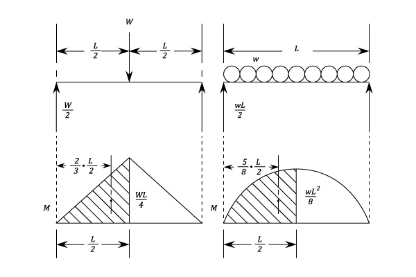
Obtain expressions for the maximum slope and deflection of a simply supported beam of span with:
a) A concentrated load at the centre.
b) With a uniformly distributed load over the whole length.
Workings
In both cases, by symmetry the slope is zero at the centre and the maximum slope and deflection can be found from the area of the Bending Moment diagram over half the beam. i.e. is at the support and is at the centre of the beam.
a) If is the area of the Bending Moment diagram for half the beam then:
Using Equation (1), Slope at support is
From Equation (2), the deflection of the support relative to the centre:
b) The area of the shaded area of the Bending Moment diagram is given by:
Using equation (1) as before, Slope at support is
From equation (2) the deflection of the support relative to the centre is given by:


 and
and  to the elastic line, cut off an intercept
  on
on  .
.
 Integrating between
 ![\left[\frac{dy}{dx} \right]_P^Q = \int \frac{M\;dx}{E\,I}](https://latex.codecogs.com/svg.image?\left[\frac{dy}{dx}&space;\right]_P^Q&space;=&space;\int&space;\frac{M\;dx}{E\,I}) If
If  is a constant then
 and since the slope everywhere is small:

 Integrating
(If
Integrating
(If  is a constant)


 with:
with:
at the centre.
over the whole length.
\left(\frac{l}{2}&space;\right)&space;=&space;\frac{Wl^2}{16}) Using Equation (1), Slope at support is
Using Equation (1), Slope at support is  From Equation (2), the deflection of the support relative to the centre:

\left(\frac{l}{2}&space;\right)&space;=&space;\frac{w\,l^3}{24}) Using equation (1) as before, Slope at support is
Using equation (1) as before, Slope at support is  From equation (2) the deflection of the support relative to the centre is given by:
\left(\frac{5}{16}l&space;\right)\left(\frac{1}{E\;I}&space;\right)=\frac{5\,w\,l^4}{384\,E\,I})
is the area of the Bending Moment diagram for half the beam then:
and the deflection is
and the deflection is