Most Engineering design is based on the "Elastic Theory of Bending" and the method is to calculate the maximum Stresses which occur, and to then keep them within the working Stresses in both compression and Tension. These working Stresses are calculated from the Yield (or ultimate) Stress and a Factor of Safety. This approach is a little unrealistic since Mild Steel Structures do not fail when the edge Stress of any cross section reaches the Yield point, and will continue to withstand the load as long as the central core of the section remains within the Elastic State.
Plastic Bending Of Beams
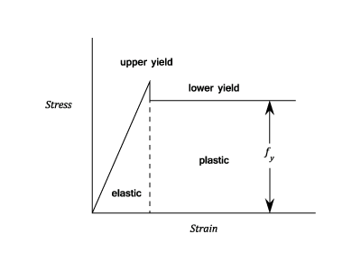
As the load on a particular beam is gradually increased, the greatest Stresses will occur at the extreme fibres of the "weakest" section (Note : In some Steels when the elastic limit is reached there is a marked reduction in Stress and in any calculations the lower Yield Stress is taken - See graph). These outer fibres are said to be in the plastic state, and any increase in loading will result in a considerable increase in Strain and hence deflection at that section of the Beam. There will also be a redistribution of Stress. With Mild Steel this increase in Strain can take place without the Stress rising above the yield point (i.e. any Strain Hardening effects can be neglected and the plastic Strain at yield is in the order of 10 - 20 times the Elastic Strain).
It can therefore be assumed that the Stress in the plastic region is Constant. When the whole cross section at any point in a structure becomes Plastic, no further increase in the moment of resistance is possible without excessive Strain (equivalent to an increase in the Curvature at that section) and a plastic hinge has been developed; one or more such hinges are required for a complete collapse. The number depends upon the type of structure and whether it is, for example, a simply supported beam, a built-in beam or a rigid frame. The value of the load required to produce this state is called the Collapse Load, and the ratio of the Collapse Load to the Working Load is called the Load Factor. In plastic design this factor is used instead of the normal Factor of Safety.
Assumptions In The Plastic Theory.
The requirement is to calculate the Bending Moment needed to form a Plastic hinge in any particular cross section, and to determine the distribution of Bending Moment along the beam at the Collapse Load. To do this it is normal to make the following assumptions:-
That the material exhibits a marked yield and can undergo considerable Strain at Yield without any further increase in Stress. In effect this limits the theory to applications using Mild Steels as the material has a drop in Stress at Yield. The lower yield stress is used in calculations.
The Yield Stress is the same in Tension and Compression.
Transverse cross-sections remain plane so that the Strain is proportional to the distance from the Neutral Axis. However, in the Plastic region the Stress will remain Constant and is not proportional to the Strain.
Once a Plastic Hinge has developed at any cross section, the Moment of Resistance at that point will remain Constant until the collapse of the whole structure has taken effect. This will only happen when the required number of Plastic Hinges at other points have developed.
The Moment Of Resistance At A Plastic Hinge.
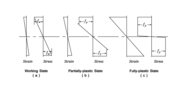
The diagram shows the variations in Stress and Strain in a beam of symmetrical cross section subjected to a working load.
(a) Using the formula from the Simple Theory of Bending, the maximum working Stress is . Note that the Stress and Strain are proportional to the distance from the Neutral Axis.
(b) The load has been increased so that the extreme fibres Yield and the beam is in a partial Plastic state. Note that is the lower Yield Stress.
(c) The Load is increased further until a fully Plastic State is obtained. It is now assumed that the stress is uniform over the whole cross section. In fact this is not strictly true, since there will be a very small elastic region around the Neutral Axis (shown on the diagram) but the effect of this on the value of the Moment of Resistance is very small and can be neglected.
Moments Of Resistance For Various Cross-sections.
a) Rectangular Section
If the width is b and the depth d then the Total loads above and below the Neutral Axis are both each acting at from the Neutral Axis. Hence, the Plastic Moment is given by:
And Z is the Normal Section Modulus.
The ratio is called the Shape Factor S since it depends only upon the Shape of the cross-section. For a rectangular section, from equations (1) and (3) :
Note that the equations (5) and (6) apply to any cross-section.
b) I-section
The Shape factor will vary slightly with the proportions of flange to web. The average value for S
is about 1.15.
c) Unsymmetrical Sections
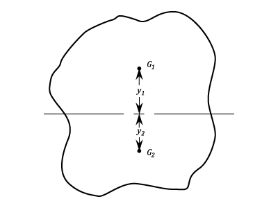
If A is the Total Area of a cross section, then it is clear that for pure Plastic Bending the
"Neutral Axis" must divide the area in half. If the Centroids of these halves are at a distance apart of ,
Example - Moments Of Resistance For Rectangular Cross-sections
Problem
A Steel bar of rectangular cross-section 3 in. by 1.25 in. is used as a simply supported beam over a span of 48 in. with a central load. If the yield Stress is 18 tons/sq.in. and the long edges of the section are vertical, (a) find the load when yielding first occurs.
Assuming that a further increase in load causes yielding to spread inwards towards the neutral axis, with the stress in the yielded part remaining at 18 tons/sq.in. , (b) find the load required to cause yielding to a depth of 0.5 in. at the top and bottom of the section at mid span. (c) Find also the length of beam over which yielding has occurred. (U.L.)
Workings
If tons is the load at first yield,then from equation (3):
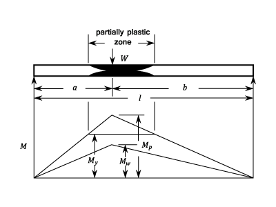
Under a higher load W the central section of the beam is in a partially Plastic state, the stress distribution being
similar to the outer 1/2 in. on each side of the neutral axis being under constant stress of 18 tons/sq.in. with no drop of stress at yield. The Moment of Resistance calculated from the stress diagram is :
(a)
(b)
(c) The length of beam over which yielding occurs
Collapse Loads
Once the Moments of Resistance at a plastic hinge in a section of a beam has been found it is necessary to decide from the conditions at the supports, how many hinges are required to cause Collapse. If there are a number of points of "local" maximum bending moments along the beam (Under working load conditions), it is clear that the first plastic hinge will occur at the numerical maximum point. If further plastic hinges are required for collapse, then these will occur at the next lower value chosen from the remaining local maxima. When sufficient plastic hinges have been formed to convert the structure into a mechanism (i.e. the hinges are considered to be pin joints), then collapse will occur.
The case of a single beam supported in three different ways will now be examined.
a) A Simply Supported Beam.
Let the load divide the length in the ratio of a:b. There is only one point of Maximum Bending Moment (i.e. Wab/l under the load) and the collapse conditions will be reached when a Plastic Hinge is formed at this point,
The Bending Moment at the hinge is , and hence the collapse Load is given by:
This is the simple result which will always be obtained when only one plastic hinge is required for collapse. For a given material and working stress it can be seen that the load factor is greater by the Shape Factor, than the normal factor of safety used on elastic design (this considers that failure occurs at first yield). It can also be seen that different load Factors will be obtained from, say, rectangular and I-sections, even under the same system of loading. Alternatively, by basing the design on a constant load factor the working Stress may be varied to suit the particular section.
The results obtained for distributed loads and for simple cantilevers are also as in equations
(29 and (30).
b) Propped Cantilever
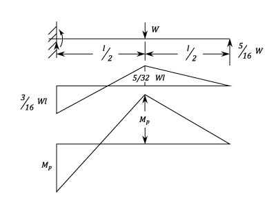
The following diagram shows a cantilever which is carrying a central load W, and which is propped at the free end to the same height as the fixed end.
The load on the prop under elastic conditions is (See pages on the deflection of beams). The Bending Moment diagram is shown immediately underneath. There are local maxima at the fixed end and under the load, and a gradual increase in load will cause a plastic hinge to form at the fixed end first as the central B.M. is somewhat less. However, due to the support at the free end,collapse conditions will not be reached until a second plastic hinge has formed under the load. At that point the B.M.'s at the centre and fixed end will be the same and numerically equal to . The distribution is shown on the lower diagram. Note that the shape of the B.M. diagram at the collapse conditions is not similar to that at Working conditions. This is due to the redistribution of Stress and Strain when a plastic hinge is formed. The value of is assumed to be the same at each hinge. If P is the load on the prop at collapse, then equating the numerical value of the B.M.'s at the fixed end and the centre gives:
This is an increase of 9:8 over a simply supported beam under the same working conditions.
c) Built in Beam with a Uniformly distributed Load.
For collapse to occur three Plastic Hinges must be formed, and as the loading is symmetrical, these will be at either end and in the centre. The Bending Moment diagram at collapse is then constructed by making the values at these points equal to . By inspection it can be seen that the reactions at the ends are and hence at the centre:
For all cases of built in beams the collapse load is not always affected by any sinking of the supports or lack of rigidity at the fixed ends, provided that the rigidity is sufficient to allow the fully plastic moment to develop.
Example:
[imperial]
Example - Application of Collapse Loads
Problem
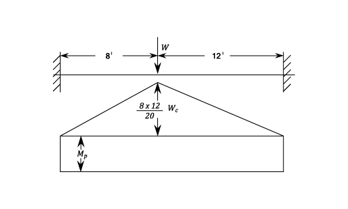
A 12 in. by 4 in. British Standard Beam is carried over a span of 20 ft. and has rigidly built in ends. Find the maximum point load which can be carried at 8 ft. from one end and the maximum working stress which will have been set up.
At collapse hinges must be formed at each end and under the load and it can be seen that the collapse load is found by equating the numerical value of the Bending Moments.
When a Beam or Column is subjected to an axial Stress as well as a Bending Stress, the neutral axis will be displaced to one side of the centroid. (a) in the following diagram shows the variation in working Stress. An increase in load will cause the stress to reach the Yield Point on one side first and then to spread across the section to give a fully plastic state (c).
It can be seen that the displacement of the neutral axis in the plastic state is given by h, where:
Comparing this to equation (6) it can be seen that the plastic moment has been reduced by a term depending upon the Axial Load, the Load Factor and the Shape of the section. The permissible working moment for a single hinge is then obtained from by dividing by the Load Factor L.
Example - Application of Combined Bending And Direct Stress
Problem
A 12 in. by 5 in. British Standard Beam has to withstand an axial load of 10 tons. If a load factor of 1.8 is to be applied, determine the maximum permissible Bending Moment.
At Collapse the axial load is 1.8 X 10 = 18 tons which requires a depth of Web of . This will be spaced equally aabout the centroid i.e. 1.705 on either side (h of equation (#49)).
The reduction in is given by the product of half the axial load and the distance between the centres of areas of each half load (i.e. GHCDJK in the above diagram)
Note that the reduction in in this case is only about %, whereas on the elastic theory, with a working stress of 10 tons/sq.in., the permissible Bending Stress is given by:
In a framework with rigid joints,under any applied load, points of maximum Bending Moment will occur at the joints. At collapse some or all of the joints will become Plastic Hinges.
The diagram shows a portal frame of height h and span l. It is under a central vertical load V and a horizontal load H. Plastic hinges may form in any combination at the points A B C D and E. It should be noted that if A and E are pin jointed, they will rotate under zero Bending Moment.
A collapse condition is reached when sufficient hinges are formed to create a "mechanism". The only three forms of collapse mechanism are:-
Beam Collapse with hinges at B, C and D.
Sway Collapse with hinges at A, B, D and E
Combined Collapse with hinges at A,C,D,and E
If one link of the mechanism is given a rotation of (under the action of the plastic moment ), then the value of the collapse load can be calculated by the principle of work, choosing the least load for all the possible mechanisms.
Some standard cases are considered below. To allow for different section beams the plastic moments will be indicated as follows:
for the stanchions AB and DE.
for the beam BD
for the corners B and D.
a) Hinged Base Portal
Vertical Load only. The symmetrical Beam Collapse will apply. A joint rotation of will occur at B and D which equates to at C. If it is assumed that the whole Strain takes place under a constant collapse load and neglecting any elastic strain, then the work done by the Load is , and the energy dissipated in the plastic hinges is . But work done must equal Energy dissipated.
Horizontal Load only. This will produce a "Sway Collapse with rotations of occurring at B and D. Equating the Work done by the load and at the plastic hinges:
Combined Load. Generally there will be no rotation at the point B and collapse will be by forming plastic hinges at C and D. The work-Energy equation now becomes:
It can be shown that if the section is uniform throughout, then if , collapse will occur by Sway. The Collapse load is given by equation (#62)
b) Fixed Base Portal
Vertical Loading only. The beam collapses in the same way as the hinged- base portal frame. Hence:
For an economical design equation (#69) and either (#67) or (#65) should be satisfied simultaneously.
Example:
[imperial]
Example - Collapse Loads In Hinged Base Portal Frames
Problem
If in the above diagram obtain an expression for the horizontal and vertical collapse loads when the Plastic moment is the same for the beam and the stanchions.
If the other two modes of collapse are checked then it will be found that they both require higher collapse loads and consequently the combined collapse mechanism gives the least load.
The most economical sections for a given load are calculated by satisfying equations (#67) and (#69) simultaneously.


. Note that the Stress and Strain are proportional to the distance from the Neutral Axis.
is the lower Yield Stress.
 tons is the load at first yield,then from equation (3):
Under a higher load W the central section of the beam is in a partially Plastic state, the stress distribution being
similar to the outer 1/2 in. on each side of the neutral axis being under constant stress of 18 tons/sq.in. with no drop of stress at yield. The Moment of Resistance calculated from the stress diagram is :
Using equation (12). At first yield the Moment of Resistance is
tons is the load at first yield,then from equation (3):
Under a higher load W the central section of the beam is in a partially Plastic state, the stress distribution being
similar to the outer 1/2 in. on each side of the neutral axis being under constant stress of 18 tons/sq.in. with no drop of stress at yield. The Moment of Resistance calculated from the stress diagram is :
Using equation (12). At first yield the Moment of Resistance is  and if
this occurs at a distance x from either end under a central load W then:
and if
this occurs at a distance x from either end under a central load W then:
 The length of beam over which yielding occurs
 (b)
(b)  (c) The length of beam over which yielding occurs

 is found by equating the numerical value of the Bending Moments.

 . This will be spaced equally aabout the centroid i.e. 1.705 on either side (h of equation (#49)).
The reduction in
. This will be spaced equally aabout the centroid i.e. 1.705 on either side (h of equation (#49)).
The reduction in  is given by the product of half the axial load and the distance between the centres of areas of each half load (i.e. GHCDJK in the above diagram)
Note that the reduction in
is given by the product of half the axial load and the distance between the centres of areas of each half load (i.e. GHCDJK in the above diagram)
Note that the reduction in  in this case is only about
  %, whereas on the elastic theory, with a working stress of 10 tons/sq.in., the permissible Bending Stress is given by:
And the reduction in
%, whereas on the elastic theory, with a working stress of 10 tons/sq.in., the permissible Bending Stress is given by:
And the reduction in 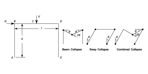
for the stanchions AB and DE.
for the beam BD
for the corners B and D.
will occur at B and D which equates to
at C. If it is assumed that the whole Strain takes place under a constant collapse load and neglecting any elastic strain, then the work done by the Load is
, and the energy dissipated in the plastic hinges is
. But work done must equal Energy dissipated.
occurring at B and D. Equating the Work done by the load and at the plastic hinges:
 obtain an expression for the horizontal and vertical collapse loads when the Plastic moment