When a geared system accelerates or decelerates there is a change in the total inertia of the system. Clearly, the value of this increase or decrease depends upon the speed ratios of the various parts of the system.
In this section we use the moments of inertia of geared shafts to identify the total torque and the Equivalent moment of Inertia for any given shaft in a state of acceleration.
The Acceleration Of Geared Systems
Acceleration is the rate of change of velocity as a function of time and it is vector. Acceleration is the second derivative of position with respect to time or, alternately, the first derivative of the velocity with respect to time.
Suppose that two shafts and are geared together and the speed ratio is
The total moments of inertia on the shafts are and
It is required to find an expression for the torque on shaft which will produce an angular acceleration of this shaft of
The torque on shaft required to accelerate is
This will produce an acceleration of shaft of
The torque required on shaft to achieve the above acceleration on is
This would require a torque on shaft of
The Total torque on is thus given by:
is called the Equivalent moment of Inertia referred to shaft .
Clearly the argument above could be extended to any number of shafts which have fixed speed ratios with the reference shaft. It is worth noting that the same acceleration of the system shown in the above diagram could be produced by a torque applied to shaft of:
The Total Kinetic Energy Of A And B
The kinetic energy of an object is the energy which it possesses due to its motion. It is defined as the work needed to accelerate a body of a given mass from rest to its stated velocity.
The Total Kinetic Energy of and
But since ,
Combined Angular And Linear Motion
There are many cases where masses moving with linear motion are connected by a fixed speed ratio to inertias in angular motion. Instead of dealing with the two motions separately, it is possible to reduce the system to one of the following:
An Equivalent Angular Motion
The angular motion is one type of motion in which a body acts as a radius and all parts of the moving body rotate in the same angular direction and follow a circular path about a pivot point.
To find the torque required to give an angular acceleration of to the winding drum of moment of inertia and radius , which is being used to raise a load on a cable wrapped round the drum.
This method is used in worked examples 2, 7, and 8.
An Equivalent Linear Motion
Linear motion is motion along a straight line, and can therefore be described mathematically using only one spatial dimension.
The linear acceleration on the level of a car of weight and engine torque , whose wheels have an inertia of and radius , and an engine with an inertia and a gear ration , is found from:
The equivalent tractive effort =
= Acceleration Equivalent mass + Losses Losses
See Example 9.
Example:
[imperial]
Example - Example 1
Problem
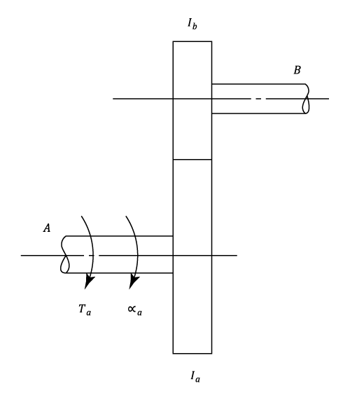
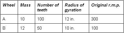
Two gear wheels and are mounted on parallel shafts so that they may revolve separately or may be meshed together externally.
The wheels were originally turning freely in the same direction.
Find:
a) The speed and direction of rotation of wheel , if the gears are suddenly meshed, assuming that there is no back-lash of the teeth.
b) The loss of energy in ft. lb. due to impact.
Workings
a) Let r.p.m. be the final speed of so that the final speed of is in the opposite direction.
The impulse is equal and opposite on the two wheels at the moment of "meshing".
By moments about their respective axes, it follows that:
The change of angular momentum of / The change of angular momentum of = The radius of / The radius of
i.e. . Or


and
are geared together and the speed ratio
is
and
is
is called the Equivalent moment of Inertia referred to shaft
 But since
  ,
,
\;\omega{_{A}}^{2})
 to the winding drum of moment of inertia
  and radius
  , which is being used to raise a load
  on a cable wrapped round the drum.
\alpha)
 , whose wheels have an inertia of
  and radius
  , and an engine with an inertia
  and a gear ration
  , is found from:
The equivalent tractive effort =
, is found from:
The equivalent tractive effort = = Acceleration
  Equivalent mass + Losses
 \left&space;(&space;W+\displaystyle\frac{g^2I_E}{r^2}&space;\right&space;)+) Losses
Losses
r.p.m. be the final speed of
in the opposite direction.