

Gear Trains
An analysis of Gear Trains with particular reference to Epicyclic Gears.
Introduction
Definitions
A gear train is a set or system of gears arranged to transfer rotational torque from one part of a mechanical system to another, with some gear ratio performing a mechanical advantage.
Epicyclic gearing or planetary gearing is a gear system consisting of one or more outer gears, or planet gears, revolving about a central, or sun gear.
Key Facts
Types of Gear Trains
- Simple Train - three or more wheels connected in series.
- Compound Train - an intermediate shaft carries two wheels connected in series.
- Tabular Method.
- The Relative Velocity Method.
- The Determination Of Torques.
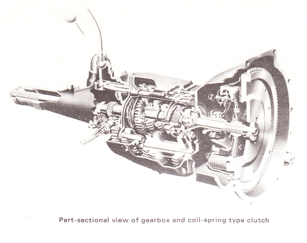
One of the most common uses of Gear Trains is in the gear boxes of cars. In the simplest form,
the crash gear box, a collection of spur gears were arranged to give different ratios of input to output speed and in the case of the reverse gear, change the direction of the output rotation.
The modern synchromesh gearbox is a development working on very similar principles.
Gear Trains On Fixed Axes
The velocity ratio transmitted between two gears is the same as for two pitch circles rolling together. As the circular pitch must be the same for both wheels, the speed ratio is determined by the number of teeth. i.e.- The positive sign is taken for Internal gearing,
- The negative sign is taken for External gearing.
A Simple train is one of three or wheels connected in series.
- The gear ratio is independent of the size of the intermediate wheels which are called Idlers
- For an odd number of externally geared wheels the direction of rotation of the last wheel is the same as the first.
- For an even number of wheels the direction of rotation of the last wheel is opposite to that of the first.
A Compound Chains
- When an intermediate shaft carries two wheels connected in series, the train becomes compound. For instance, if
gears with
, which is compounded with
, which then drives
.
- Where the axis of the last wheel is in line with that of the first, the arrangement is known as a reverted train.
Epicyclic Trains.
One or more of the wheels of the gear train are now carried on an arm which itself rotates about the axis of the main wheels.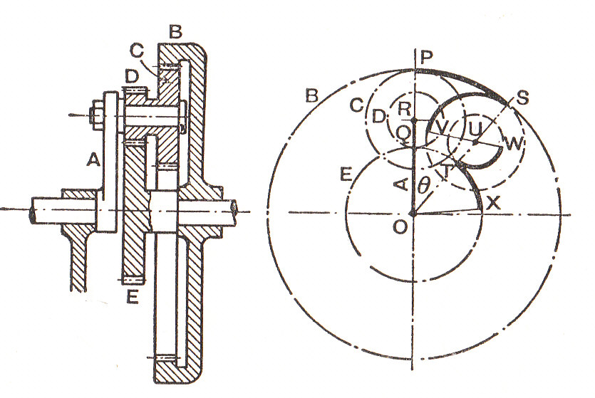
The central main wheel is called the Sun wheel. The wheels carried by the arm are known as the Planet wheels and the outside internal wheel is called the Annulus. In some epicycilic gear trains the "arm" has a number of "limbs," each carrying a planet wheel. In these cases the "arm" may be referred to as the Spider.
There are a number of ways of analysing epicyclic gear trains. Three are described here:Tabular Method
- The first line of the table is obtained by fixing the arm and then giving one wheel (e.g. the wheel which is to be fixed later) one revolution.
- Write down the corresponding revolutions of the other wheels from their number of teeth.
- As all the wheels and the arm can be turned about the same axis, an equal number of revolutions may be added (or subtracted) from each wheel.
- Any two lines may be multiplied (or divided) through by the same factor.
- Any two lines may be combined. By these means the given conditions are satisfied and the resulting gear ratio can be determined.
The Relative Velocity Method
- If the arm is fixed, then the gear becomes a simple or compound train. Thus the ratio of the speeds of any two wheels can be determined by using the methods of paragraph (2).
i.e.
(If the arm were fixed.)
Where there is an intermediate shaft between
The Determination Of Torques
- There are normally three torques acting on an epicyclic gear. These are:
Alternatively, the forces acting on each wheel (or compound pair) may be analysed separately since if the gear is running at constant speed, there is no resultant force and no resultant torque on any intermediate wheel.
the input Torque (in the sense of rotation of the input shaft)
the output torque (opposite to the sense of rotation of the output shaft)
the Torque on the casing.
From considerations of the power and for equilibrium ( Taking signs into account )
- For input and output shafts to have the same direction of rotation
- For input and output to have opposite directions of rotation.
And,
Example:
[imperial]
Example - Example 1
Problem
Two shafts and in the same line are geared together through an intermediate parallel shaft . The wheels connecting and have a diametral pitch of 9 and those connecting and 4, the least number of teeth on any wheel being not less than 15. The speed of is to be about but not greater than  the speed of and the ratio of each reduction is the same.
Find suitable wheels, the actual reduction and the distance of shaft from and .
Find suitable wheels, the actual reduction and the distance of shaft
Workings
Since the speed ratios between and and between and are to be the same and the overall reduction is greater than 12 then, using and adapting equation (1)
 i.e.
As and are in a straight line, the centre distance between each and must be the same. Also the diametral pitches are 9 and 4.
i.e.
i.e.
As and are in a straight line, the centre distance between each and must be the same. Also the diametral pitches are 9 and 4.
i.e.  From the Speed Ratios
  and
and  Substituting into equation (1),
 t_{C2}) And
And t_B) It follows that
It follows that  is the lesser and since it must be an even number greater than 15, try
  . Then
  from the speed ratio.