This section on Inertia Forces and Couples should be read in conjunction with those covering Velocity and Acceleration. There you will find details of both velocity and acceleration diagrams and Klein's construction and all these are used in the Worked Examples.
Inertia Forces
If the centre of gravity of a body of mass has a linear acceleration , then the resultant of the external forces acting on the body must be . It follows that the external forces would be in equilibrium with a force of in the opposite direction.
Inertia is the resistance of any physical object to a change in its state of motion or rest, or the tendency of an object to resist any change in its motion. It is proportional to an object's mass.
Centre of gravity is the point in or near a body at which the gravitational potential energy of the body is equal to that of a single particle of the same mass located at that point, and through which the resultant of the gravitational forces on the component particles of the body acts.
A force is any influence that causes a free body to undergo a change in speed, a change in direction, or a change in shape. Force can also be described by intuitive concepts such as a push or pull that can cause an object with mass to change its velocity, i.e., to accelerate, or which can cause a flexible object to deform.
This latter force is called the Inertia Force and it is numerically equal to the product of mass and acceleration of the centre of gravity. It acts in the opposite direction to the acceleration.
The system of external forces and inertia forces is treated as if in statical equilibrium. Note that the use of centrifugal force in governor problems is a particular example of this principle.
Inertia Couples
If the angular acceleration of a body is , then in addition to the Inertia Force at the centre of gravity there is an Inertia Couple, where is the moment of Inertia about the centre of gravity. As above, the direction of the inertia couple is opposed to the angular acceleration.
If the body is turning about a fixed axis , then the inertia force and couple can be combined into a couple of magnitude
The inertia force and couple may be reduced to a single force of magnitude which acts in a parallel direction at a distance
It was shown in " Velocity and Acceleration Equation(20)" that the acceleration of the piston is given by:
where is measure from the inner dead-centre position and the negative sign indicates that the acceleration is towards the crank. Thus, if is the mass of the reciprocating parts,
Inertia Force
Where is the force of the gas on the piston and is towards the crank.
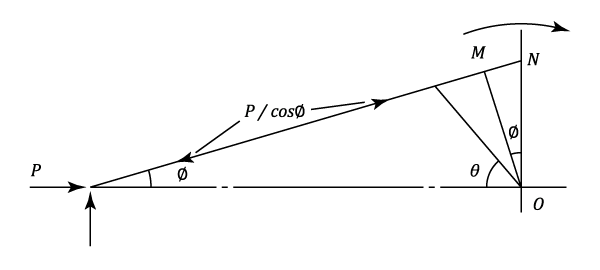
It can be seen from the diagram that is accompanied by a force in the connecting-rod of , and the useful turning moment on the crankshaft during the power or outstroke is,
On the instroke the turning moment in the direction of rotation is with the other senses remaining as before (See example 1)
The Inertia Of The Connecting-rod.
The linear acceleration of the centre of gravity, , and the angular acceleration can be found graphically by using the method described in "Velocity and Acceleration," or by Klien's construction. The Inertia Force and the Couple can then be calculated and reduced to a single force at a distance from the centre of gravity (See paragraph 2).
Assuming that the reaction at the small end is perpendicular to the line of stroke, the reaction at the big end, and hence the turning moment on the crank due to the inertia of the connecting-rod, can be determined (See example 3).
The Equivalent Two-mass System
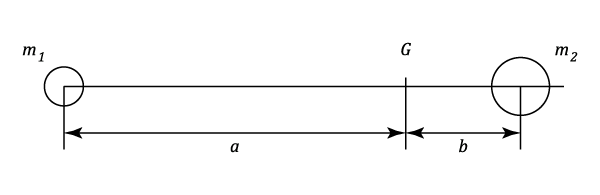
Any body of total mass can be replaced dynamically by two "point" masses and at distances and respectively from the centre of gravity. The choice of the masses and their positions must satisfy the following conditions:
i.e., the new system has the same mass, the same position, and the same moment of inertia as the original.
The method of solving these equations is either to :
Fix one of the masses. This allows equations (5) (6) and (7) to be solved and give,
Fix and and calculate the two masses. This allows the calculation of and from equations (5) and(6) only.
In applying to a connecting-rod it is normal to fix and place it at the small end where it can be added to the reciprocating parts. will lie near to the big end and may be added to the rotating parts for a first approximation.
Example:
[imperial]
Example - Example 1
Problem
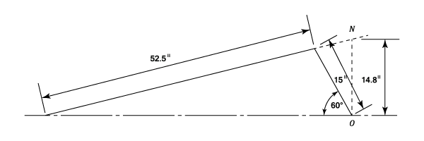
A horizontal steam engine running at 240 r.p.m. has a bore of 15 in. and a stroke of 30 in. The connecting rod is 52.5 in. long and the reciprocating parts weigh 120 lb. When the crank is at past its inner dead-centre, the steam pressure on the covered side of the piston is 90 p lb/sq.in. while that on the crank side is 10 lb/sq/in.
Neglecting the area of the piston rod, determine:
a) The force in the piston rod.
b) The turning moment on the crankshaft.
Workings
From the given dimensions , , and
a) Using equation (3)
b) This part of the question has a graphical solution.


, then the inertia force and couple can be combined into a couple of magnitude
which acts in a parallel direction at a distance
is measure from the inner dead-centre position and the negative sign indicates that the acceleration is towards the crank. Thus, if
is the mass of the reciprocating parts, Inertia Force and the effective force along the line of the crank
is given by, Where
is the force of the gas on the piston and is towards the crank.
, and the useful turning moment on the crankshaft during the power or outstroke is, On the instroke the turning moment in the direction of rotation is
with the other senses remaining as before (See example 1)
, and the angular acceleration
can be found graphically by using the method described in "Velocity and Acceleration," or by Klien's construction. The Inertia Force and the Couple can then be calculated and reduced to a single force
from the centre of gravity (See paragraph 2). Assuming that the reaction at the small end is perpendicular to the line of stroke, the reaction at the big end, and hence the turning moment on the crank due to the inertia of the connecting-rod, can be determined (See example 3).
 past its inner dead-centre, the steam pressure on the covered side of the piston is 90 p lb/sq.in. while that on the crank side is 10 lb/sq/in.
Neglecting the area of the piston rod, determine:
past its inner dead-centre, the steam pressure on the covered side of the piston is 90 p lb/sq.in. while that on the crank side is 10 lb/sq/in.
Neglecting the area of the piston rod, determine:
 ,
,  , and
, and 
)
\frac{\pi&space;}{4}\times&space;15^2-\frac{120\times&space;15}{32.2\times&space;12}\left&space;(&space;\frac{240\times&space;2\,\pi&space;}{60^2}&space;\right&space;)^2\left&space;(&space;0.5-\frac{0.5}{3.5}&space;\right&space;))