Definitions:Controlling Force is the inward radial force exerted on each ball of a centrifugal governor by the arms, spring, etc. which are attached to it. At any equilibrium speed the controlling force is equal and opposite to the centrifugal force.
Effort is the mean force exerted at the sleeve due to a 1% change in the speed of the governor.
Power is the work done at the sleeve for a 1% change in speed. It is called "The Power" and is equal to the effort times the sleeve displacement.
Sensitivity is defined as the ratio of the mean speed to the speed range of the governor over its limits of operation.
Stability: A governor is said to be stable if there is one equilibrium speed for each radius of rotation and this speed increases with the radius. i.e.
Isochronism: A governor is said to be isochronous if, neglecting friction, the equilibrium speed is the same for all radii of the balls. This implies infinite sensitivity and the governor will always fly to one or other extreme position.
Hunting: The governor is said to hunting if the engine speed is caused to fluctuate continually above and below the mean speed. This is caused by over-compensation of the energy supply due to the governor being too sensitive.
The function of a Governor is totally different to that of a Flywheel. The former is required to control the mean speed of a engine over a period of time as opposed to a flywheel which is used to limit the almost inevitable fluctuations in speed, which occur during one cycle.
A good example of this is the single cylinder Four stroke engine. There is only one power stroke to two revolutions of the crankshaft. Without a flywheel, the speed would either fluctuate by an unacceptable amount within one cycle, or the engine would not work at all since the energy stored in the flywheel is required to carry the engine through to the next Power Stroke.
A Boulton and Watt Rotative Engine made in 1797.
The Watt type Governor can be seen at the top of the picture.
A change in load on a engine will almost certainly lead to a change in speed and the Governor is required to alter the supply of energy to the engine to bring the speed back to its original value. This is achieved by connecting the rotating parts of the governor, through suitable levers, to a sleeve on its axis of rotation. Any change in the speed causes a change in the position of the rotating parts and consequently to the sleeve and this movement actuates the fuel supply valve (this includes compressed air,steam or water) of the particular engine or turbine. This function is of particular importance in A.C. electric generators since it is important to maintain the correct number of cycles per second from the generator who's load may change rapidly and unpredictably.
Generally Governors can be classified as either Centrifugal or Inertia.
Centrifugal Governors
The effort of the governor is obtained from the change in centrifugal force on (usually) two rotating masses known as Balls, when an increase or decrease in governor speed occurs.
Two main types can be distinguished.
Dead-weight Governors
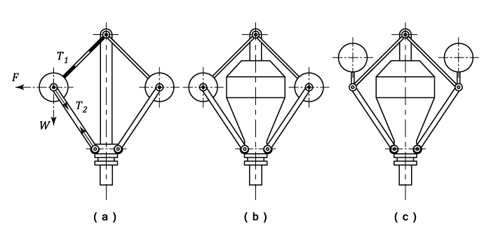
The radius of the ball path is controlled by lever and weights the latter being usually attached to the sleeve as in the Watt (a) Porter (b) or Proell (c) governors.
The equilibrium position can usually be determined by considering the forces acting on one ball and the arm (or arms) to which it is attached. ( See Examples 1,2 and 5)
Spring-loaded Governors.
The balls are controlled by springs acting on them or the sleeve. Three examples are shown in the diagram.
The Hartnell governor (a) is a well known example of this type. Each ball is attached at one end of a bell-crank lever and at the other end to the actuating sleeve. The method of analysis is to take moments about the pivot of the lever.
( See Examples 6,7 and 8)
Inertia Governors
Inertia Governors work on a different principle. The governor balls are arranged so that the inertia forces caused by angular acceleration or retardation of the governor shaft tend to alter their positions. The amount of the displacement of the balls is controlled by springs and the governor mechanism to alter the supply of energy to the engine.
The advantage of this type of Governor is that the positions of the balls are affected by the rate of change of speed of the governor shaft. Consequently, a more rapid response to a change of load is obtained, since the action of the governor is due to acceleration and not to a finite change of speed. The advantage is offset, however, by the practical difficulty of
arranging for a complete balance of the revolving parts of the governor. For this reason
centrifugal governors are much more frequently used. ( See Example 10)
Example:
[imperial]
Example - Example 1
Problem
The upper arm of a loaded governor are 11 in. long and are pivoted on the axis of rotation.
The lower arms are also 11 in. long between pin joints but are pivoted to the sleeve at distances of in. from the axis of rotation. Each governor ball weighs 12 lb. and is carried on an extension of the lower arm, the ball centre being vertically above and in. from the pin joint between the upper and lower arms when the radius of gyration is 8 in.
Neglecting friction, find the load required on the sleeve in order to give an equilibrium speed of 270 r.p.m. for this radius of gyration.
Workings
The forces acting on one half of the governor are shown in the diagram. Neglecting inertia effects in the upper arms, the reaction at must be in the direction of .
Taking moments about the intersection of produced and the horizontal through , the reaction at and the horizontal component at are eliminated.
The triangles and are similar
The centrifugal forces on one of the balls :
Taking moments about for the lower arm and ball:


 and this speed increases with the radius. i.e.
 ) Isochronism: A governor is said to be isochronous if, neglecting friction, the equilibrium speed is the same for all radii of the balls. This implies infinite sensitivity and the governor will always fly to one or other extreme position.
Hunting: The governor is said to hunting if the engine speed is caused to fluctuate continually above and below the mean speed. This is caused by over-compensation of the energy supply due to the governor being too sensitive.
Isochronism: A governor is said to be isochronous if, neglecting friction, the equilibrium speed is the same for all radii of the balls. This implies infinite sensitivity and the governor will always fly to one or other extreme position.
Hunting: The governor is said to hunting if the engine speed is caused to fluctuate continually above and below the mean speed. This is caused by over-compensation of the energy supply due to the governor being too sensitive.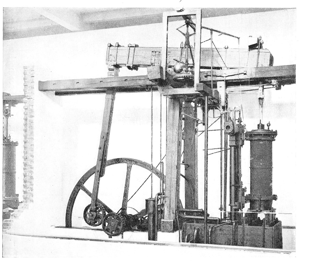
 The Hartnell governor (a) is a well known example of this type. Each ball is attached at one end of a bell-crank lever and at the other end to the actuating sleeve. The method of analysis is to take moments about the pivot of the lever.( See Examples 6,7 and 8)
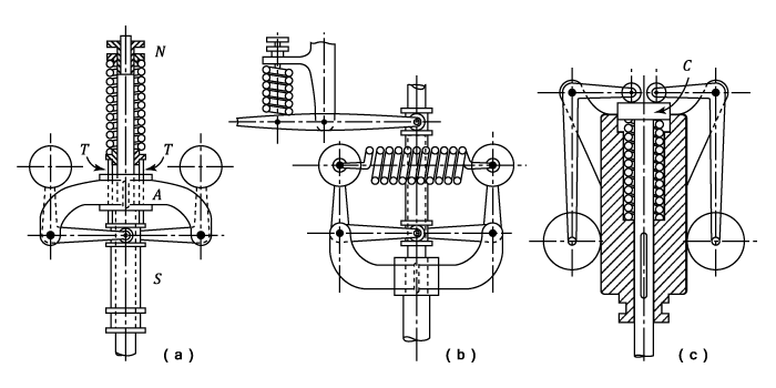
 in. from the axis of rotation. Each governor ball weighs 12 lb. and is carried on an extension of the lower arm, the ball centre being vertically above and
  in. from the pin joint between the upper and lower arms when the radius of gyration is 8 in.
Neglecting friction, find the load required on the sleeve in order to give an equilibrium speed of 270 r.p.m. for this radius of gyration.
in. from the pin joint between the upper and lower arms when the radius of gyration is 8 in.
Neglecting friction, find the load required on the sleeve in order to give an equilibrium speed of 270 r.p.m. for this radius of gyration.
 must be in the direction of
  .
.
 produced and the horizontal through
  , the reaction at
 The triangles
  and
and  are similar
 The centrifugal forces on one of the balls :
 ^2) Taking moments about
Taking moments about  for the lower arm and ball:
^2\times&space;12.2-12\times9,2)


